Episode 02. Straight Pipe under Internal Pressure
Summary
In this episode, we introduce the stresses due to internal pressure and discuss how to determine the straight pipe wall thickness under internal pressure based on these stresses. Finally, we compare it to the method for determining pipe wall thickness in ASME B31.3 code.
1. Introduction
In the previous episode, we discussed how to determine the internal diameter of a pipeline. However, choosing a pipe requires determining the wall thickness. Minimum thickness is essential to withstand the various stresses encountered during operation. Wall thickness that is too thin can cause pipe failure. So, we need to select an appropritate thickness that balances economy and safety.
Then, how do we determine the pipe thickness? Pipes under internal pressure must withstand the stresses due to the pressure. In this episode, we describe the normal stresses due to internal pressure and discuss how we can use these stresses to determine the pipe wall thickness.
2. Stresses due to internal pressure
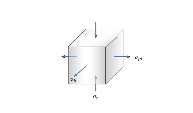
Let’s discuss the normal stresses that can act on straight pipes. (Figure 2.1) illustrates the stresses acting on the pipe walls. We can confirm that the stresses of the pipe wall can classified into three types: Hoop stress, Longitudinal stress, and Radial stress. To calculate these stresses, we utilize the fact that forces are in equilibrium in each direction.
\( {\small\displaystyle\begin{align} \sum F \quad=\quad 0 \tag*{} \end{align} } \)

(Figure 2.1)

(Figure 2.2)
Hoop Stress (\({\small\displaystyle \sigma_h}\))
It is also known as circumferential stress, which can be calculated based on the equilibrium with the force exerted by internal pressure. The force on the pipe wall is due to hoop stress, while the force on the pipe cross-sectional area is due to internal pressure. Hence, we can establish the following relationship: Here, \({\small\displaystyle A_1}\) represents the area corresponding to the pipe wall, and \({\small\displaystyle A_2}\) is the pipe cross-sectional area.
\( {\small\displaystyle\begin{gather} \sigma_hA_1 \,=\, PA_2 \quad\longrightarrow\quad \sigma_h(2tL) \,=\, P(D_iL) \\[15pt] \sigma_h \quad=\quad \frac{PD_i}{2t} \quad=\quad \frac{P\left(D_o\,-\,2t\right)}{2t} \tag{Eq 2.1} \end{gather} } \)

(Figure 2.3)
Longitudinal Stress (\({\small\displaystyle \sigma_l}\))
The stress acting in the longitudinal direction of the pipe is a combination of three components: Bending stress, stress caused by axial forces, and caused by internal pressure.
\( {\small\displaystyle\begin{align} \sigma_l \quad=\quad \sigma_b\,+\, \sigma_{dl}\,+\, \sigma_{pl} \tag{Eq 2.2} \end{align} } \)
Let’s take a closer look at the stress induced by internal pressure, \({\small\displaystyle\sigma_{pl}}\).
\( {\small\displaystyle\begin{gather} \sigma_{pl}\left[\frac{\pi\left(D_o^2\,-\,D_i^2\right)}{4}\right] \quad=\quad P\left(\frac{\pi D_i^2}{4}\right) \\[15pt] \sigma_{pl} \quad=\quad \frac{PD_i^2}{4D_mt},\quad\left(D_m\,=\,\frac{D_o\,+\,D_i}{2}\right) \tag{Eq 2.3} \end{gather} } \)

(Figure 2.4)
Radial Stress (\({\small\displaystyle \sigma_r}\))
The stress acting on the pipe wall in the radial direction can be represented as shown in (Figure 2.4). This stress reaches its maximum when \({\small\displaystyle r\,=\,r_i}\) and its minimum when \({\small\displaystyle r\,=\,r_o}\).
Assume the pipe wall is thin and the ambient pressure is atmospheric (gauge pressure is zero). Then, the stress becomes almost identical to the internal pressure.
\( {\small\displaystyle\begin{align} \sigma_r \quad=\quad \alpha P \,\approx\, P \tag{Eq 2.4} \end{align} } \)
3. Pipe wall thickness & ASME B31.3
We can deduce the suitable thickness of the pipe to withstand the internal pressure based on the stresses due to the internal pressure discussed above. According to the Maximum Shear Stress Theory (or Tresca theory), the maximum shear stress becomes half the difference between the maximum and minimum of the three principal stresses.
\( {\small\displaystyle\begin{gather} \sigma_1 \quad\gt\quad \sigma_2 \quad\gt\quad \sigma_3 \\[10pt] \tau_{max} \quad=\quad \frac{\sigma_1\,-\,\sigma_3}{2} \tag*{} \end{gather} } \)
Using the theory, the maximum shear stress in the tensile test of the material is:
(In the tensile test \({\small\displaystyle \sigma_1\,=\,S_y, \,\text{and }\,\sigma_{2},\,\sigma_{3}\,=\,0}\))
\( {\small\displaystyle\begin{align} \tau_{max} \quad=\quad \frac{S_y}{2} \tag{Eq 2.5} \end{align} } \)
(Figure 2.5)
Now, let’s calculate the maximum shear stress due to internal pressure in the pipe wall. Assume that the magnitude of radial stress is smaller than the magnitude of longitudinal stress.
\( {\small\displaystyle\begin{gather} \sigma_h \quad\gt\quad \sigma_{pl} \quad\gt\quad \sigma_r \\[15pt] \frac{PD_o}{2t}\,-\,P \quad\gt\quad \frac{PD_i^2}{4D_mt} \quad\gt\quad \alpha P \tag*{} \end{gather} } \)
The longitudinal stress due to internal pressure follows the relationship.
\( {\small\displaystyle\begin{align} \frac{PD_i^2}{4D_mt} \quad=\quad \frac{PD_o^2}{4D_mt}\,-\,P \quad&\gt\quad \frac{PD_o}{4t}\,-\,P \tag*{} \end{align} } \)
If the right-hand side of above relationship is larger than the \({\small\displaystyle \sigma_r}\), we can infer that the \({\small\displaystyle \sigma_{pl}}\) is naturally larger than the \({\small\displaystyle \sigma_r}\).
\( {\small\displaystyle\begin{gather} \frac{PD_o^2}{4D_mt}\,-\,P \quad\gt\quad \frac{PD_o}{4t}\,-\,P \quad\gt\quad \alpha P \tag{Eq 2.6} \\[15pt] D_o/t \quad\gt\quad 4(1\,+\,\alpha) \tag{Eq 2.7} \end{gather} } \)
When the \({\small\displaystyle D_o/t}\) exceeds a certain value, we can calculate the maximum shear stress that can act on the pipe wall. (Stress is indicated with a negative sign when compression and with a positive sign when tension.)
\( {\small\displaystyle\begin{align} \tau_{max} \quad&=\quad \frac{\sigma_h\,-\,\sigma_r}{2} \\[15pt] &=\quad \frac{1}{2}\left[\frac{PD_o}{2t}\,-\,(1\,-\,\alpha)P\right] \tag{Eq 2.8} \end{align} } \)
Based on (Eq 2.5) and (Eq 2.8), we can derive the relationship between the yield strength of the material and the internal pressure.
\( {\small\displaystyle\begin{align} \frac{S_y}{2} \quad&=\quad \frac{1}{2}\left[\frac{PD_o}{2t}\,-\,(1\,-\,\alpha)P\right] \\[15pt] S_y \quad&=\quad \frac{PD_o}{2t}\,-\,(1\,-\,\alpha)P \tag{Eq 2.9} \end{align} } \)
Looking at the form of (Eq 2.9), we can observe a similarity to the method used to determine pipe thickness under internal pressure in the ASME B31 code. Let’s multiply factors \({\small\displaystyle E}\) and \({\small\displaystyle W}\) on the \({\small\displaystyle S_y}\) in (Eq 2.9) to account for the impact of the manufacturing method, and the effect of the material’s long-term strength when welding. Then, substituting \({\small\displaystyle \,y\,}\) for \({\small\displaystyle \,1\,-\,\alpha\,}\) and rearranging the left-hand side to \({\small\displaystyle \,t\,}\), we can obtain the formula for determining the wall thickness of straight pipe under internal pressure, which is found in the ASME B31.3.
\( {\small\displaystyle\begin{align} S_yEW \quad&=\quad \frac{PD_o}{2t}\,-\,yP \\[15pt] t \quad&=\quad \frac{PD_o}{2(SEW\,+\,yP)} \tag{Eq 2.10} \\[15pt] t_m \quad&=\quad t\,+\,c \tag{Eq 2.11} \end{align} } \)
In ASME B31.3, we use (Eq 2.10) for calculating \({\small\displaystyle t}\) when \({\small\displaystyle t<D_o/6}\). Then, the minimum required wall thickness of pipe is determined by adding \({\small\displaystyle c}\), the sum of mechanical, corrosion, and erosion allowances, to \({\small\displaystyle t}\) in (Eq 2.10).
(Figure 2.6)
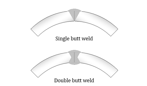
Quality factors, \({\small\displaystyle E}\), consider the influence of piping manufacturing. \({\small\displaystyle E}\) can be divided into casting quality and weld joint quality factors. For casting methods, the value is influenced by the material used, while for welding joint methods, the welding type primarily influences to determine this value.
For \({\small\displaystyle W}\), it’s a factor that considers the weakening of the long-term strength of the material at the welded joint compared to the original material caused by temperature elevated during welding. This value tends to decrease as the temperature rises.
We can find detailed values for \({\small\displaystyle E,\,W}\), and \({\small\displaystyle y}\) in the ASME B31.3 document.
Nomenclature
\({\small\displaystyle A}\) : area
\({\small\displaystyle c}\) : the sum of mechanical, corrosion, and erosion allowances
\({\small\displaystyle D_i}\) : inner diameter
\({\small\displaystyle D_m}\) : mean diameter
\({\small\displaystyle D_o}\) : outer diameter
\({\small\displaystyle E}\) : quality factors
\({\small\displaystyle F}\) : force
\({\small\displaystyle L}\) : length
\({\small\displaystyle P}\) : pressure
\({\small\displaystyle S}\) : allowable stress of material
\({\small\displaystyle t}\) : wall thickness
\({\small\displaystyle t_m}\) : minimum required wall thickness
\({\small\displaystyle W}\) : weld joint strength reduction factors
\({\small\displaystyle y}\) : coefficient
\({\small\displaystyle \alpha}\) : coefficient
\({\small\displaystyle \sigma_b}\) : bending stress
\({\small\displaystyle \sigma_h}\) : hoop stress
\({\small\displaystyle \sigma_l}\) : longitudinal stress
\({\small\displaystyle \sigma_{dl}}\) : longitudinal stress due to direct force
\({\small\displaystyle \sigma_{pl}}\) : longitudinal stress due to internal force
\({\small\displaystyle \sigma_r}\) : radial stress
\({\small\displaystyle \tau}\) : shear stress
Reference
The American Society of Mechanical Enginners. ASME B31.3 , Process Piping. B31.3 – Process Piping | 2022 | ASME