Episode 03. Centrifugal Pump - Working Principle
Summary
In this episode, we describe the principle of a centrifugal pump, one of the types of pumps. We start by briefly understanding centrifugal force and explain the key components: the impeller, the diffuser (or volute), and more. Based on the velocity triangles within the impeller, we’ll focus on discussing how centrifugal pumps increase the liquid’s energy.
1. Introduction
In Episode 01, we mentioned there are various types of pumps. In this episode, we describe the type known as the centrifugal pump. As the name suggests, this pump utilizes centrifugal force to transport fluids. Let’s take a look at rotational motion before discussing the centrifugal pump. (Figure 3.1) illustrates an object undergoing rotational motion around a circle with a radius r. We can calculate various physical values as follows.
| Angular velocity | \( {\small\displaystyle\begin{align} \omega \quad=\quad \frac{d\theta}{dt} \end{align} } \) |
| Arc length | \( {\small\displaystyle\begin{align} s \quad=\quad r\theta \end{align} } \) |
| Tangential velocity | \( {\small\displaystyle\begin{align} v \,=\, \frac{dL}{dt} \,=\, r\omega \end{align} } \) |
| Centripetal force | \( {\small\displaystyle\begin{align} F_{centripetal} \,=\, \frac{mv^2}{r} \,=\, mr\omega^2 \end{align} } \) |
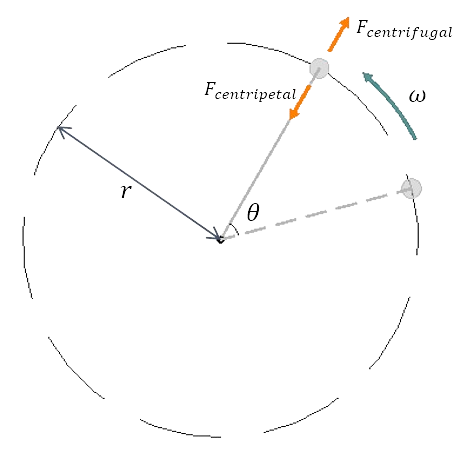
(Figure 3.1)
Here, the centrifugal force (\({\small\displaystyle F_{centrifugal}}\)) is a fictitious force with the same magnitude as the centripetal force but in the opposite direction. Now, let’s explore the principles and components of a centrifugal pump.
2. Working principle & Components
The working principle of a centrifugal pump is as follows. First, the impeller connected to the shaft rotates by a motor (or drive). Then, the liquid, energized by the rotating impeller, passes the diffuser or volute and is discharged.
As mentioned, the main components of a centrifugal pump include an impeller and a diffuser (or volute).
Impeller
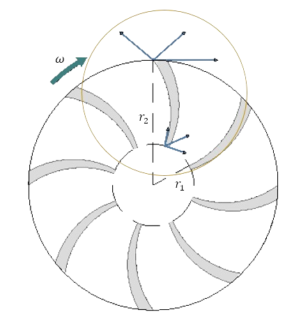
(Figure 3.2)

(Figure 3.3)
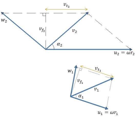
The impeller’s role is to transfer energy from the motor to the liquid. The liquid which passages the impeller inlet moves outward of the impeller due to centrifugal force. As the liquid moves outward, its energy (or head) increases. To discuss this in detail, let’s analyze the velocity triangles at each point. The values of each vector in the velocity triangles are presented in (Figure 3.3). We can calculate the angular momentum(L) supplied by the motor as the difference between the angular momentum at the impeller’s outlet (2) and inlet (1) points.
\( {\small\displaystyle\begin{align} \mathrm{L}_{supply} \quad&=\quad \mathrm{L}_2\,-\,\mathrm{L}_1 \tag*{} \end{align} } \)
Angular momentum is determined by multiplying the radius and linear momentum. Thus, the equation becomes as follows.
\( {\small\displaystyle\begin{align} \mathrm{L}_{supply} \quad&=\quad \mathrm{p}_2r_2\,-\,\mathrm{p}_1r_1 \\[10pt] &=\quad m\left(v_{t_2}r_2\,-\,v_{t_1}r_1\right),\qquad \mathrm{p}\,=\,mv_t \tag{Eq 3.1} \end{align} } \)
When differentiating (Eq 3.1) with respect to time, we can obtain the torque. Additionally, by multiplying torque by angular velocity (\({\small\displaystyle \omega}\)), we can derive the power of the pump motor. Dividing both sides of (Eq 3.3) by mass flow rate (\({\small\displaystyle \dot{m}}\)) gives us energy per unit mass supplied by the pump. When expressing \({\small\displaystyle E_{supply}}\) in terms of head, we refer to it as Euler head(\({\small\displaystyle H_e}\)) or ideal head.
\( {\small\displaystyle\begin{align} \tau_{supply} \quad&=\quad \dot{m}\left(v_{t_2}r_2\,-\,v_{t_1}r_1\right) \tag{Eq 3.2} \\[15pt] \mathrm{P}_{supply} \quad&=\quad \dot{m}\left(u_2v_{t_2}\,-\,u_1v_{t_1}\right),\qquad u\,=\,\omega r \tag{Eq 3.3} \\[15pt] E_{supply}(\,=\,gH_e) \quad&=\quad u_2v_{t_2}\,-\,u_1v_{t_1} \tag{Eq 3.4} \end{align} } \)
We can express the absolute velocity in the tangential direction as follows.
\( {\small\displaystyle\begin{align} w_2^2\,-\,\left(u_2\,-\,v_{t_2}\right)^2 \,=\, v_2^2\,-\,v_{t_2}^2 \quad&\longrightarrow\quad v_{t_2} \,=\, \frac{v_2^2\,-\,w_2^2\,+\,u_2^2}{2u_2} \\[15pt] w_1^2\,-\,\left(u_1\,-\,v_{t_1}\right)^2 \,=\, v_1^2\,-\,v_{t_1}^2 \quad&\longrightarrow\quad v_{t_1} \,=\, \frac{v_1^2\,-\,w_1^2\,+\,u_1^2}{2u_1} \tag*{} \end{align} } \)
Therefore, we can rearrange (Eq 3.4) to (Eq 3.5).
\( {\small\displaystyle\begin{align} &E_{supply} \quad=\quad \underbrace{\frac{v_2^2\,-\,v_1^2}{2}}_{1)}\,+\, \underbrace{\frac{w_1^2\,-\,w_2^2}{2}}_{2)}\,+\, \underbrace{\frac{u_2^2\,-\,u_1^2}{2}}_{3)} \tag{Eq 3.5} \\[15pt] &\text{1) The change in kinetic energy of the liquid} \\[10pt] &\text{2) The effect of the passage diffusion} \\[10pt] &\text{3) The effect of the centrifugal energy} \end{align} } \)
In axial flow, the centrifugal effect decreases. On the other hand, in radial flow, the change in \({\small\displaystyle w}\) is minimal. Typically, the liquid’s velocity is higher at the impeller’s outlet compared to the inlet.
Diffuser & Volute
The fluid, increased energy (or head) due to the impeller, passes through a diffuser or a volute. At this time, as the fluid’s velocity decreases, the kinetic energy is converted to the pressure energy. This relationship can be easily verified using the Bernoulli equation.
\( {\small\displaystyle\begin{align} \frac{v_A^2}{2}\,+\,gh_A\,+\,\frac{P_A}{\rho} \quad=\quad \frac{v_B^2}{2}\,+\,gh_B\,+\,\frac{P_B}{\rho} \tag*{} \end{align} } \)
\({\small\displaystyle A}\) signifies the outlet from the impeller, while \({\small\displaystyle B}\) denotes the outlet from the volute. We know the fluid velocity is lower at point \({\small\displaystyle B}\) compared to \({\small\displaystyle A}\). If there is no difference in height between these points, the pressure at point \({\small\displaystyle B}\) will be higher than that at point \({\small\displaystyle A}\).
Efficiency
The Euler head is the value in ideal conditions. However, the actual head differs from the Euler head due to several factors. Therefore, we calculate the actual head using efficiency as we consider the efficiency of the pump work in Episode 01. We can infer that the overall efficiency will be determined by how much energy from the shaft is transferred to the fluid. We can express it in the following equation.
\( {\small\displaystyle\begin{align} \eta_o \quad=\quad \frac{\rho gQH}{\mathrm{P}_s} \tag{Eq 3.6} \end{align} } \)
The head in the above equation refers to the actual head of the liquid. We can rearrange the equation as (Eq 3.7).
(\({\small\displaystyle Q_I}\): the volume flow rate of liquid discharged from the impeller, \({\small\displaystyle Q_L}\): the liquid flow leaking from the impeller, \({\small\displaystyle \mathrm{P}_I}\) : the power through the impeller.)
\( {\small\displaystyle\begin{align} \eta_o \quad&=\quad \frac{\rho g\left(Q_I\,+\,Q_L\right)H_e}{\mathrm{P}_s}\cdot \frac{Q_I}{Q_I\,+\,Q_L}\cdot \frac{H}{H_e} \\[10pt] &=\quad \frac{\mathrm{P}_I}{\mathrm{P}_s}\cdot \frac{Q_I}{Q_I\,+\,Q_L}\cdot \frac{H}{H_e} \\[10pt] &=\quad \underbrace{\eta_m}_{1)}\cdot \underbrace{\eta_v}_{2)}\cdot \underbrace{\eta_h}_{3)}\cdot \tag{Eq 3.7} \end{align} } \)
(Eq 3.7) shows that it consists of the 1)mechanical efficiency, 2)volumetric efficiency, and 3)hydraulic efficiency.
Nomenclature
\({\small\displaystyle F}\) : force
\({\small\displaystyle g}\) : gravitational accerlation
\({\small\displaystyle h}\) : height
\({\small\displaystyle H}\) : head
\({\small\displaystyle \mathrm{L}}\) : angular momentum
\({\small\displaystyle m}\) : mass
\({\small\displaystyle p}\) : linear momentum
\({\small\displaystyle \mathrm{P}}\) : power
\({\small\displaystyle P}\) : pressure
\({\small\displaystyle Q}\) : volume flow rate
\({\small\displaystyle r}\) : radius
\({\small\displaystyle v}\) : velocity
\({\small\displaystyle \rho}\) : density
\({\small\displaystyle \eta}\) : pump efficiency
\({\small\displaystyle \tau}\) : torque