
Episode 06. Reciprocating Pump - Working Principle
Summary
The reciprocating pump is a well-known type of positive displacement pump, often considered when pumping high-viscosity fluids or when high pressure is needed. In this episode, we look at the basic principles and key features of reciprocating pumps and discuss the additional factors for calculating NPSH in these pumps.
1. Introduction
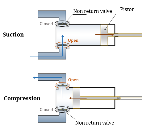
(Figure 6.1)
Reciprocating pumps are positive displacement pump that uses linear motion to transport fluids. We consider using this type of pump when pumping high-viscosity fluids or when high pressure is required. However, since only a fixed volume of fluid is transported, there is a limitation on the flow rate.
Reciprocating pumps operate by repeating two steps, suction and compression, to transport fluids. (Figure 6.1) shows each stage of reciprocating pumps. During suction, the piston (or plunger) moves to the right, opening the non-return valve on the suction side and closing the non-return valve on the discharge side. The piston (or plunger) then compresses a set amount of fluid, discharging the fluid. During this process, the non-return valve on the suction side closes, and the non-return valve on the discharge side opens.
2. Working principle of reciprocating pumps
Let’s take a reciprocating pump with a crank as an example and look at its various features. As shown in (Figure 6.2), we define the distance moved by the piston (or plunger) from the point of maximum compression as \({\small\displaystyle x}\), the crank radius as \({\small\displaystyle r}\), the crank rotational speed as \({\small\displaystyle \omega}\), and the length of the connecting rod as \({\small\displaystyle l}\).

(Figure 6.2)
Distance, Velocity & Acceleration
First, let’s calculate the distance \({\small\displaystyle x}\). Based on (Figure 6.2), we can derive \({\small\displaystyle x}\) as shown in (Eq 6.1).
\( {\small\displaystyle\begin{align} x \quad&=\quad (r\,+\,l)\,-\,\left(\sqrt{l^2\,-\,r^2\sin^2\theta}\,+\,r\cos\theta\right) \\[10pt] &=\quad r(1\,-\,\cos\theta)\,+\,l\left(1\,-\,\sqrt{1\,-\,\frac{r^2}{l^2}\sin^2\theta}\right) \tag{Eq 6.1} \end{align} } \)
Using (Eq 6.1), we can plot a graph of \({\small\displaystyle \theta}\) and \({\small\displaystyle x}\). When \({\small\displaystyle \theta}\) ranges from \({\small\displaystyle 0}\) to \({\small\displaystyle \pi}\), the system is in the suction phase, and when \({\small\displaystyle \theta}\) ranges from \({\small\displaystyle \pi}\) to \({\small\displaystyle 2\pi}\), it is in the compression phase. Additionally, when \({\small\displaystyle \theta}\) is \({\small\displaystyle \pi}\), \({\small\displaystyle x}\) reaches its maximum value, the crank diameter.
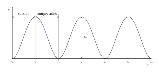
(Figure 6.3)
Second, we can calculate the linear velocity and acceleration of the piston (or plunger) using the crank’s rotational speed \({\small\displaystyle \omega}\).
\( {\small\displaystyle\begin{align} \frac{dx}{dt} \quad&=\quad \frac{dx}{d\theta}\cdot\frac{d\theta}{dt} \,=\, \frac{dx}{d\theta}\cdot\omega \\[15pt] v \quad&=\quad r\left(\sin\theta\,+\,\frac{\sin 2\theta}{2\sqrt{\dfrac{l^2}{r^2}\,-\,\sin^2\theta}}\right)\omega \quad\cong\quad r\left(\sin\theta\,+\,\frac{\sin 2\theta}{2(l/r)}\right)\omega \tag{Eq 6.2} \\[15pt] \frac{dv}{dt} \quad&=\quad \frac{dv}{d\theta}\cdot\frac{d\theta}{dt} \,=\, \frac{dv}{d\theta}\cdot\omega \\[15pt] a \quad&=\quad r\left(\cos\theta\,+\,\frac{r\cos 2\theta}{l}\right)\omega^2 \tag{Eq 6.3} \end{align} } \)
Volumetric flow rate
Assuming the cross-sectional area of the piston (or plunger) is \({\small\displaystyle A}\), we can calculate the volumetric flow rate using (Eq 6.2). Set the discharged flow rate as positive value. Then, the velocity is in the opposite direction when calculating the volumetric flow rate.
\( {\small\displaystyle\begin{align} Q \quad=\quad -Ar\left(\sin\theta\,+\,\frac{r\sin 2\theta}{2l}\right)\omega \tag{Eq 6.4} \end{align} } \)
Let’s plot a graph of \({\small\displaystyle \theta}\) and \({\small\displaystyle Q}\) .
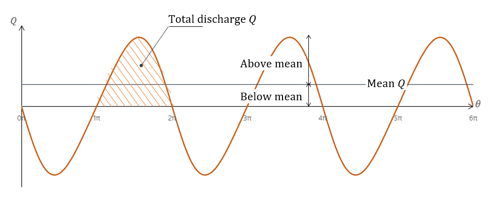
(Figure 6.4)
The total discharge flow rate in 1 cycle is equal to the area of the graph from \({\small\displaystyle \pi}\) to \({\small\displaystyle 2\pi}\). Therefore, we can express the mean flow rate for a single-acting reciprocating pump as (Eq 6.5).
\( {\small\displaystyle\begin{align} Q_{avg} \quad&=\quad \frac{1}{2\pi}\int_{\pi}^{2\pi}\,-Ar\left(\sin\theta\,+\,\frac{r\sin 2\theta}{2l}\right)\,d\theta \\[10pt] &=\quad \frac{Ar\omega}{\pi} \tag{Eq 6.4} \end{align} } \)
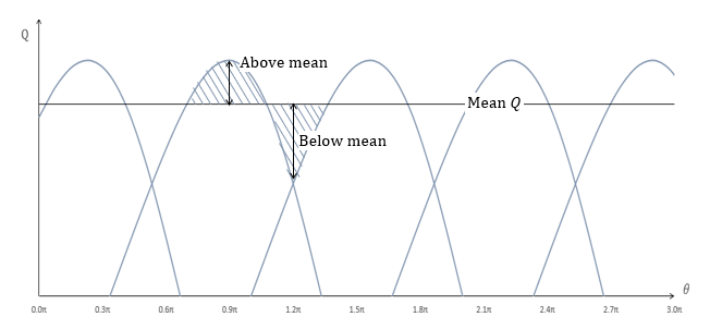
(Figure 6.4) shows that the reciprocating pumps don’t discharge a constant volumetric flow rate. It means there is pulsation in the system, and the phenomenon can cause vibrations and noise. Therefore, it is necessary to supply the flow as constantly as possible. Using a double-acting mechanism instead of a single-acting one, increasing the number of pistons (or plungers), or installing a dampener downstream of the pump are representative methods.
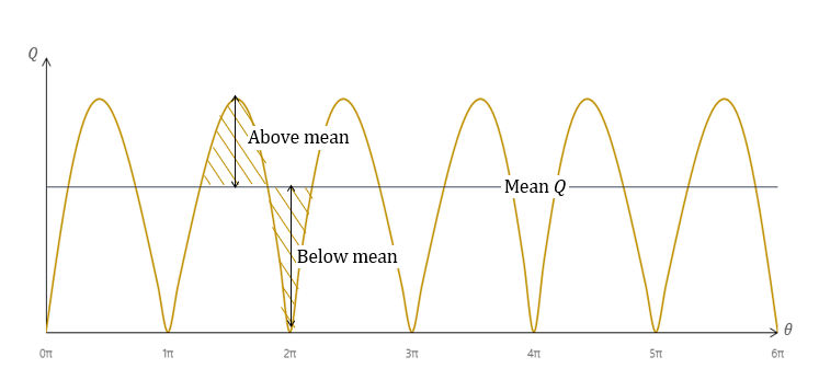
(Figure 6.5)
(Figure 6.6)
(Figure 6.5) shows the graph of \({\small\displaystyle \theta}\) and \({\small\displaystyle Q}\) for a double-acting reciprocating pump, and (Figure 6.6) illustrates the same for a triplex reciprocating pump (three pistons). Looking at (Figure 6.5) and (figure 6.6), we can see that the shaded areas above and below the mean flow rate are equal in each graph.
The key point here is that the deviation from the mean flow rate is gradually decreasing.
3. Acceleration pressure head
In a reciprocating pump, the fluid does not flow continuously. So, it is necessary to consider pressure head loss due to the instantaneous acceleration of the fluid. The acceleration pressure head also impacts the calculation of NPSH, covered in Episode 02.
We mainly use (Eq 6.6) to calculate the acceleration head on the suction side of a reciprocating pump.
The value of \({\small\displaystyle C}\) in (Eq 6.6) varies depending on the pump type. The value decreases as the number of pistons (or plungers) increases. In other words, as the number of pistons increases, the acceleration head loss decreases. We can find detailed values for each variable of (Eq 6.6) in API STD 674.
\( {\small\displaystyle\begin{align} h_{acc} \quad=\quad \frac{LVNC}{Kg} \tag{Eq 6.6} \end{align} } \)
\( {\small\displaystyle\begin{align} L \,&:\, \text{Actual length of suction line}\,[m] \\[10pt] V\,&:\, \text{Average liquid velocity}\,[m/s] \\[10pt] N\,&:\, \text{Pump crankshaft speed}\,[RPM] \\[10pt] C\,&:\, \text{Pump type constant} \\[10pt] K\,&:\, \text{Constant depending on fluid compressibility} \end{align} } \)
Applying (Eq 6.6) to calculate \({\small\displaystyle NPSH_a}\), we can express the equation as follows.
\( {\small\displaystyle\begin{align} NPSH_a \quad=\quad h_{ss}\,-\,h_{fs}\,-\,h^v\,-\,h_{acc} \tag{Eq 6.7} \end{align} } \)
Nomenclature
\({\small\displaystyle A}\) : cross sectional area
\({\small\displaystyle a}\) : accerleration
\({\small\displaystyle c}\) : pump type constant
\({\small\displaystyle g}\) : gravitational acceleration
\({\small\displaystyle h_{acc}}\) : acceleration head
\({\small\displaystyle h_f}\) : friction head
\({\small\displaystyle h_{ss}}\) : statif suction head
\({\small\displaystyle h^v}\) : vapor pressure head
\({\small\displaystyle K}\) : constant depending on fluid compressibility
\({\small\displaystyle L}\) : actual length of suction line
\({\small\displaystyle l}\) : length of connecting rod
\({\small\displaystyle N}\) : speed
\({\small\displaystyle NPSH}\) : net positive suction head
\({\small\displaystyle Q}\): volumetric flow rate
\({\small\displaystyle r}\): crank radius
\({\small\displaystyle t}\) : time
\({\small\displaystyle v}\) : velocity
\({\small\displaystyle \theta}\) : angle
\({\small\displaystyle \omega}\) : crank rotational speed, rad/s